- comparison.jpg (63.89 KiB) Viewed 1422 times
- comp processed.jpg (302.91 KiB) Viewed 1422 times
- stack.jpg (106.63 KiB) Viewed 1422 times


I am not sure to have understood the mod you suggest, it seems you mean the following: sun--> scope --> ERF --> barlow --> filter --> DCX --> camera, however a Barlow is a diverging lens while in the pictures I see the aperture placed between two converging lenses. Do you mean is the second filter that shall be placed between the DCX's ?justapictureposter wrote: ↑Sat Mar 13, 2021 1:25 pmAs seen on this image, the small filter becomes the "aperture" and the image space and object space become parallel through it..
Hi Apollo,The narrowband filter itself, should be placed between these 2 optics. It is a quick an easy double telecentric and This made the spicule layer and prominences explode into view... I cannot explain how it works, but it does.

Sorry Apollo, but since you have chosen to put this up on a public forum I feel obligated to let folks know your posts regarding macro telecentric lens systems applied to what you are doing with a Barlow lens (regardless of the number of elements) and a single element telecompressor lens are most surely inaccurate: While the triple element Barlow might coincidentally be reducing aberration at 394 mn, there is no way to know without a real-word optical element ray-trace analysis. Additionally, there is no such thing as a "parallel image;" "telescope vision" optics design results are different from "industrial vision schematics;" there is no way to tell that your triple element Barlow and positive singlet "produces 'tandem [telecentric] system operation';" nor would it be applicable to what you are doing for the placement of the CaK filter inside the Barlow lens housing where you appear to assume you are getting a collimated output, followed by the singlet telecompressor lens - which therefore is totally irrelevant to the performance of the filter, and is also likely not a telecentric output.... the collimated bundle, forms a parallel image at the center of the aperture. The terminology is called "tandem operation" in the optics world. and industrial vision schematics is no different from telescope vision schematics; albeit one is macro and one is telephoto. Lens operation becomes very different when multiple groups are incorporated outside of he standard pcx singlet + pcv combo. We are dealing with a focal point in this situation.
An achromat objective + the barlow creates a new "positive lens group" with a new focal point (the focal point being the image of the sun cast onto the aperture), the barlow also alters the focal point operation of the 100mm element ; from what i see with my eye it has reduced down to just 25mm (the size of my extension).
The design on the apochromatic triplet barlow brings all points of light from the objective to the same focal point at the center of the aperture in the center of the barlow, and when the DCX lens is focused on the center of this aperture point of focus it produces "tandem system operation", . Emphasis added.
This is an accurate statement. While we all appreciate your endeavors to seek "new" solutions to CaK and H alpha filter implementations, given the self-admitted lack of knowledge about optical theory, unless one can produce a valid ray-trace that shows what is actually happening with your specific optics, one should not be making any specific optical system claims or conclusions. This is the exact type of unfounded speculation and misinformation we should be striving to discourage, not encourage.I know little about lens theory, and maybe someone with actual prescription knowledge can figure it out;

Yes Marty :-)
Thanks Christian,christian viladrich wrote: ↑Tue Mar 16, 2021 12:57 pmYes Marty :-)
The basic formulae are there (near the bottom of this page):
As a matter of fact, I've done an extensive study (kind of feasibility) for a project of a 1 A Ca K filter. There are various issues at stake :
- CWL of the Ca K filter => this is in relation with the issue of sweet spot formation with tilt,
- change of CWL with temperature => this is related to change of FWHM with tilt and the need or not to have a thermoregulated filter,
- change of FWHM and CWL with f-ratio and field angle => this is related to the need (or not) for a telecentric beam.
Basically, filters with FWHM < about 1.5A are a bit tricky to use, there is no free lunch ;-)
If you think this could help, I can put some info/data in a web page.
I'm not sure I'm fully understanding what you mean by using a collimator system to create a long EFR and introduce a telecentric aspect after that. You would typically just employ a telecentric system to create the long EFR and and use one or more filters in the telecentric output of the system. I guess you could use a collimator for one filter, and make the refocusing lens a telecentric element for an additional filter or filters. But you could just as easily avoid the Jacquinot spot effects of the collimator filter - and just employ a long EFR telecentric system alone with multiple filters.In a collimator type system, with a really long focal-length (F16~F32+) and relatively small aperture (say 60mm~80mm tops), one can generate a really long focal-ratio. So I'm curious if this can be further used to benefit the FWHM of a narrowband filter, and if so, by about how much (the calcs). Then, would it be useful to then introduce telecentriscm to this train and its effects. Then, could a 2nd or 3rd filter be stacked, that are not ultra rare and hard to get, to get a very selective final transmission profile centered on CaK line.
Sorry, just worded poorly, I'm just curious if these can be effectively utilized or even combined with a narrow filter to effect its FWHM and how a stack could interact when both are treated this way. For example, could a single filter be utilized with combinations of the above; versus two filters stacked (but at what FWHM and in what setup would be ideal). A lot of optics just seem really poorly corrected for 393nm, so I've tried to avoid amplifiers, barlows, etc, and resorted to simply using truly long focal-lengths from long physical scopes and reducing aperture to generate a small light cone instead that way. So I'm curious how this drives the bandpass of the filter (my Lunt CaK for example) and what I could do to improve it (if I can), versus adding another filter (and if so, what FWHM would be needed, versus ideal).Bob Yoesle wrote: ↑Tue Mar 16, 2021 5:29 pm Hi Marty,
I'm not sure I'm fully understanding what you mean by using a collimator system to create a long EFR and introduce a telecentric aspect after that. You would typically just employ a telecentric system to create the long EFR and and use one or more filters in the telecentric output of the system. I guess you could use a collimator for one filter, and make the refocusing lens a telecentric element for an additional filter or filters. But you could just as easily avoid the Jacquinot spot effects of the collimator filter - and just employ a long EFR telecentric system alone with multiple filters.In a collimator type system, with a really long focal-length (F16~F32+) and relatively small aperture (say 60mm~80mm tops), one can generate a really long focal-ratio. So I'm curious if this can be further used to benefit the FWHM of a narrowband filter, and if so, by about how much (the calcs). Then, would it be useful to then introduce telecentriscm to this train and its effects. Then, could a 2nd or 3rd filter be stacked, that are not ultra rare and hard to get, to get a very selective final transmission profile centered on CaK line.I believe Christian does this when he uses his DayStar and Coronado SMn quartz etalon double stacked H alpha filter system.

Thanks George, interesting!george9 wrote: ↑Wed Mar 17, 2021 1:49 am Just to point out that an f/30 refractor is better than f/7.5, but neither is as good as an f/7.5 with a TZ4 telecentric element (see Christian's web site). So it is not just getting to the specified f/ratio, but how you get there.
On Bob's comment, I do use a collimator followed by a telecentric for H-alpha just because that was easiest to cobble together, not because it is ideal. The sweet spot drops from 32mm SS to about 28mm DS, which is good enough for me.
PST CaK's do show up occasionally. I got one on AM about two years ago. They pop up about that often. Mine was rusted in every element except the desired #1 yellow filter. I inserted it in my B1200 CaK. There was extra room on the eyepiece end, so a properly threaded ring holds it in place, with some shims for slight tilt.
I should really get a TZ3 for my AP155 (potentially stopped down). Same lens prescription as the AP130 f/8.3. I guess something like a TOA would be better, but that's a real expense. My trial-and-error attempts at Barlows have never worked in CaK.
George

Hello Christian,christian viladrich wrote: ↑Thu Mar 11, 2021 9:33 am Excellent. Thanks for sharing !
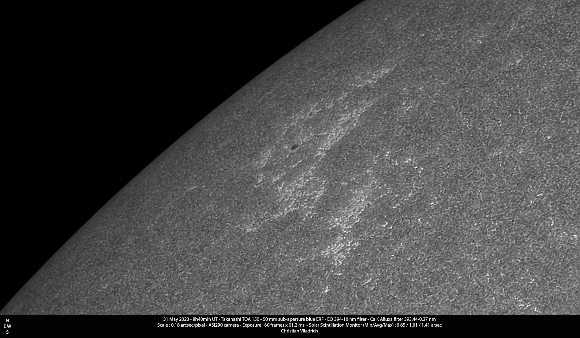
In addition to the image of yours and Bob's images, here is another comparison.
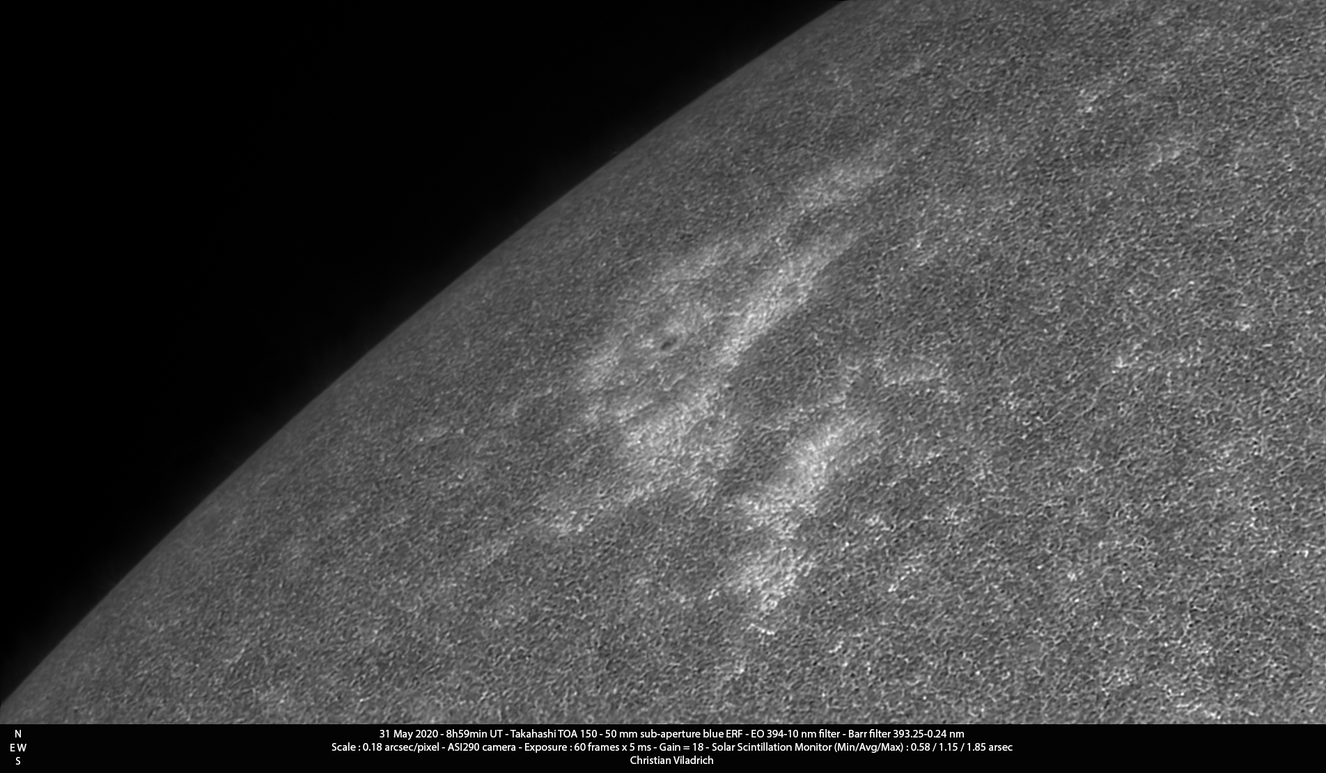
First one with a 0.37 A FWHM Ca K filter :
http://astrosurf.com/viladrich/astro/so ... ASI290.jpg
Then a 0.24 nm FWHM :
http://astrosurf.com/viladrich/astro/so ... ASI290.jpg
The layer of the chromosphere is a bit higher, so the small pore is less visible.The frontier of the bright plages become a bit fuzzier (because magnetic tubes are expanding with height).
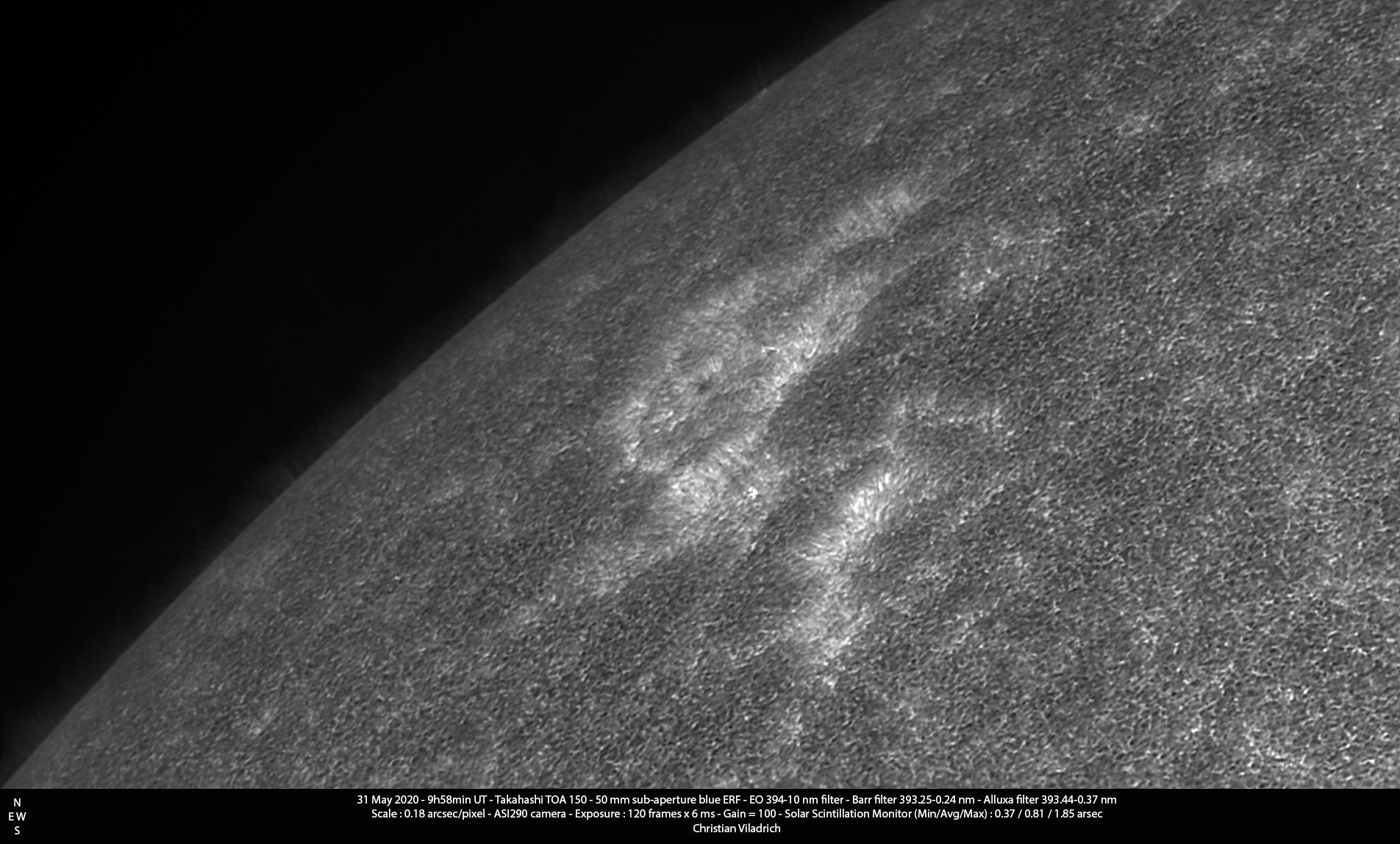
Double stack 0.37 A + 0.24 A filters :
http://astrosurf.com/viladrich/astro/so ... ASI290.jpg
Here we get higher in the chromosphere. The pore is virtually hiden by the canopy. Vertical fibrils become visible in the bright plages.
christian viladrich wrote: ↑Thu Mar 11, 2021 9:33 am Excellent. Thanks for sharing !
In addition to the image of yours and Bob's images, here is another comparison.
First one with a 0.37 nm FWHM Ca K filter :// correction of units made on March, 13
http://astrosurf.com/viladrich/astro/so ... ASI290.jpg
Then a 0.24 nm FWHM :
http://astrosurf.com/viladrich/astro/so ... ASI290.jpg
The layer of the chromosphere is a bit higher, so the small pore is less visible.The frontier of the bright plages become a bit fuzzier (because magnetic tubes are expanding with height).
Double stack 0.37 nm + 0.24 nm filters :// correction of units made on March, 13 /u]
http://astrosurf.com/viladrich/astro/so ... ASI290.jpg
Here we get higher in the chromosphere. The pore is virtually hiden by the canopy. Vertical fibrils become visible in the bright plages.

Hi Ken,
Interesting, so your surface filaments on the disc are easy to notice and not just subtle?
Hi Ken,When the seeing cooperates I can record filaments in CaK as well as the occasional prom.